One of the main job of an OS is managing the movement of data between input/output (I/O) devices. This management is performed by the kernel’s I/O subsystem.
Most I/O devices fit into the following categories:
- storage devices
- transmission devices (Bluetooth, network connections)
- human-interface devices
A controller is an electronic component (as simple as a chip or as complex as a circuit board (aka host adapter) that can operate a port, a bus, or a device. They may contain a processor, registers, microcode, and private memory.
In order to support a plethora of devices the kernel uses device-driver modules. The device drivers present a uniform interface between the I/O device controller and the kernel, just as system calls provide a standard interface between user applications and the kernel.
Busses
A device communicates with a computer system by sending signals and data over a wired bus or through the air. A bus is a set of wires with a rigidly defined protocol that specifies a set of messages that can be sent over the bus.
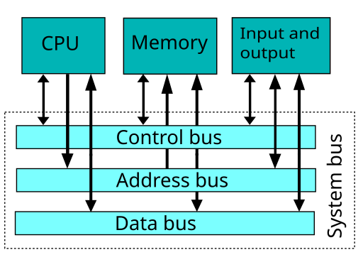
The system bus connects the CPU with RAM and other busses. Some of the wires on the system bus are used to send control signals, others send address information, and others send data as shown below.
The image below shows the bus configuration on a motherboard.
Buses vary in their:
- protocol
- connection method
- signaling method
- signaling speed
A common bus found on many computers is the PCI bus. It connects fast devices (IDE disk controllers, graphics controller) to the processor-memory subsystem. Slower devices such as a keyboard, parallels port and serial ports are connected to an expansion bus that is connected to the PCI bus through an expansion bus controller or bridge.
A device connects to a bus through a connection point or port consisting of a set of wire endpoints. Ports can be external (serial, keyboard) or be on internal component.
Communicating between the Processor and the Controllers
The processor communicates with controllers using one of the following:
- using special I/O instructions and addresses that trigger the bus controller to select the proper device and to move bits into or out of a controller’s registers.
- the controller’s device-control registers are mapped to main memory. The processor uses standard data-transfer read and write instructions to perform memory-mapped I/O.
The graphics controller usually uses both: I/O ports for control operations, and memory-mapped I/O for screen contents.
Interrupts
It is most efficient if the controller notifies the CPU when the device becomes ready for service. An interrupt is the hardware mechanism that allows one component in the computer to notify another that an event has occurred.
Interrupts can be issued for the following events:
- system exception (divide by zero)
- accessing protected memory
- controller raised exceptions (ready for service, service complete, error)
- software interrupt or trap (via library functions to execute system calls)
- managing resources by the kernel (run process in waiting queue since device is now ready)
Essentially, the CPU has an input wire called the interrupt-request line that the CPU reads after every instruction. When the CPU detects a signal on the line, it performs a state save and jumps to the interrupt-handler routine at a fixed address in memory. The interrupt handler then
- determines the cause of the interrupt
- performs the necessary processing
- performs a state restore
- executes a return from interrupt instruction to return the CPU to state before the interrupt.
Hundreds of interrupts are sent per second and most computer systems have a more sophisticated interrupt handling mechanism to
- defer interrupt handling during critical processing
- distinguish between high and low priority interrupts
These features are provided by an interrupt-controller. Most CPUs have two interrupt-request lines:
- unmaskable for high priority events
- maskable for low priority events. The CPU can wait on interrupts on this line.
Device controllers use the maskable line.
The interrupt controller accepts an address (offset) in an interrupt vector table which specifies the type of interrupt. The table specifies a chain of addresses of interrupt handlers. When an interrupt occurs, the interrupts in the chain are executed until one is found that can handle the interrupt.
At boot time, the operating system probes the hardware busses to determine which devices are present and installs the corresponding interrupt handlers into the interrupt vector.
A Partial Interrupt Vector Table
| 0 | divide error (handler sends exception to user program) |
| 5 | bound range exception |
| 14 | page fault (page needed from virtual memory) |
| 16 | floating point error |
| 32-255 | maskable interrupts |
© 2017, Eric. All rights reserved.

